Removing an interior wall in a pre-war Manhattan residence is fundamentally different from opening up a suburban partition. Behind the vintage plaster and wire lath often lies multi-wythe common brick, heavy structural steel, or secondary framing carrying accumulated dead load from century-old terracotta flat arches. In landmarked cooperatives along Central Park West, Park Avenue, and Riverside Drive, taking down a partition demands rigorous structural analysis, non-deflecting temporary shoring, and seamless navigation through both the NYC Department of Buildings (DOB) and co-op alteration review panels.
At TRD Builders, our in-house licensed Professional Engineers (PE) and construction crews approach every wall opening as a major structural transfer. Here is the exact field protocol we execute on Manhattan jobsites to eliminate settlement risk and guarantee board approval.
Structural Systems in Pre-War NYC Architecture (1890–1940)
Manhattan residential architecture evolved rapidly across five decades. Identifying the building era dictates exactly what you will encounter behind the plaster:
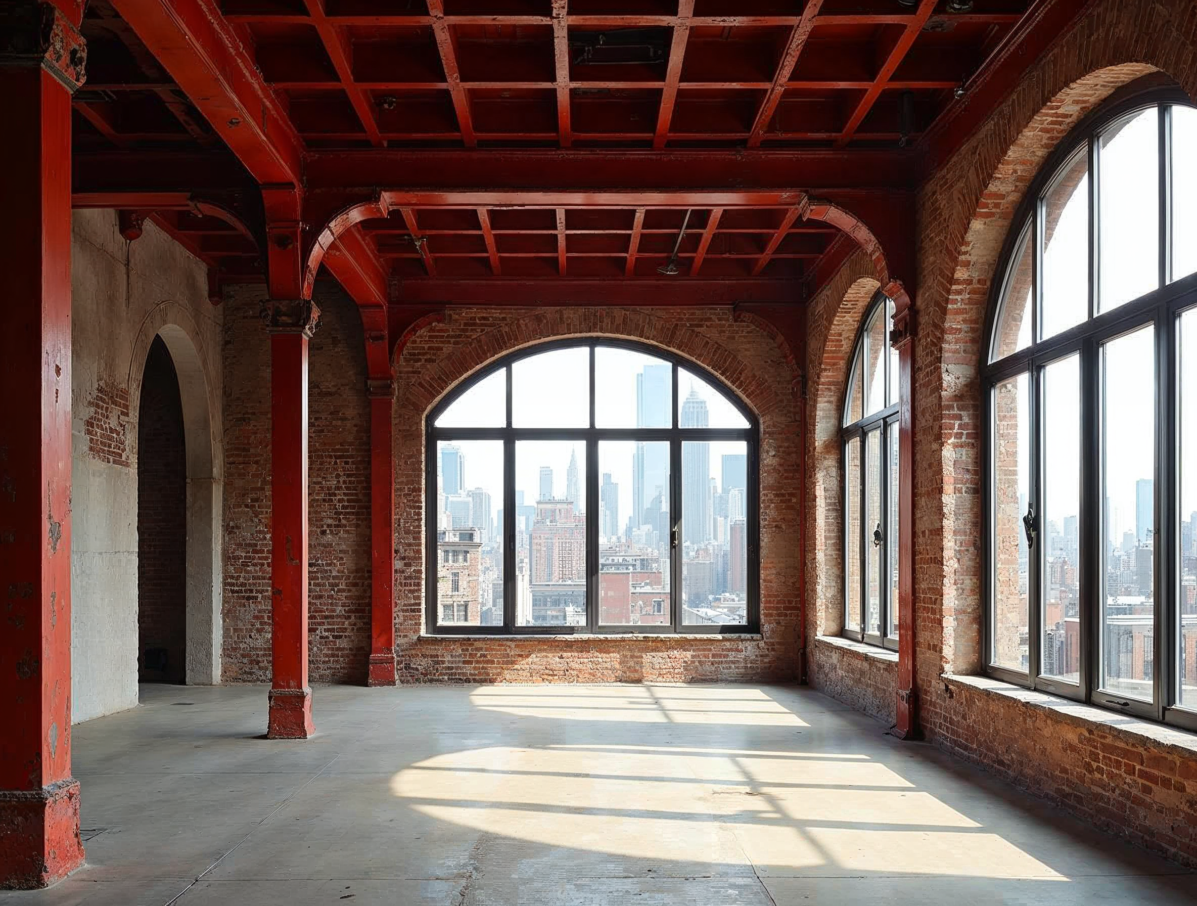
- Unreinforced Masonry & Cast Iron (pre-1905): Multi-wythe load-bearing brick walls support heavy timber joists or cast-iron and wrought-iron beams. Many interior corridor walls serve as critical bearing lines or shear walls.
- Steel Skeleton with Flat-Arch Terracotta Floor Slabs (1901–1928): Structural steel frames carry hollow clay tile flat arches. While primary loads transfer to exterior columns and interior steel stanchions, secondary partition walls often carry decades of accumulated dead-load deflection from the floor above.
- Cinder Concrete Floor Arches (1910–1940s): Wire-mesh reinforced cinder concrete draped over structural I-beams. Partition walls in these buildings often brace long-span floor beams or conceal active building mechanical risers.
Demolition without exploratory investigation is reckless. Before drafting structural plans, our engineering team executes selective exploratory probes—removing small sections of plaster at the ceiling line and partition corners to measure joist bearing depths, verify flange widths, and confirm whether the wall supports structural loads from the floor above.
Engineering Protocols: Shoring and Temporary Load Transfer
Transferring the gravity loads of multiple stories above requires a temporary support system that prevents even a fraction of an inch of settlement. In vintage plaster ceilings, 1/16-inch of differential movement will crack decorative moldings on the floor above and immediately trigger a co-op stop-work order.
Temporary Shoring Towers and Needle Beams
Before any masonry or stud framing is demolished:
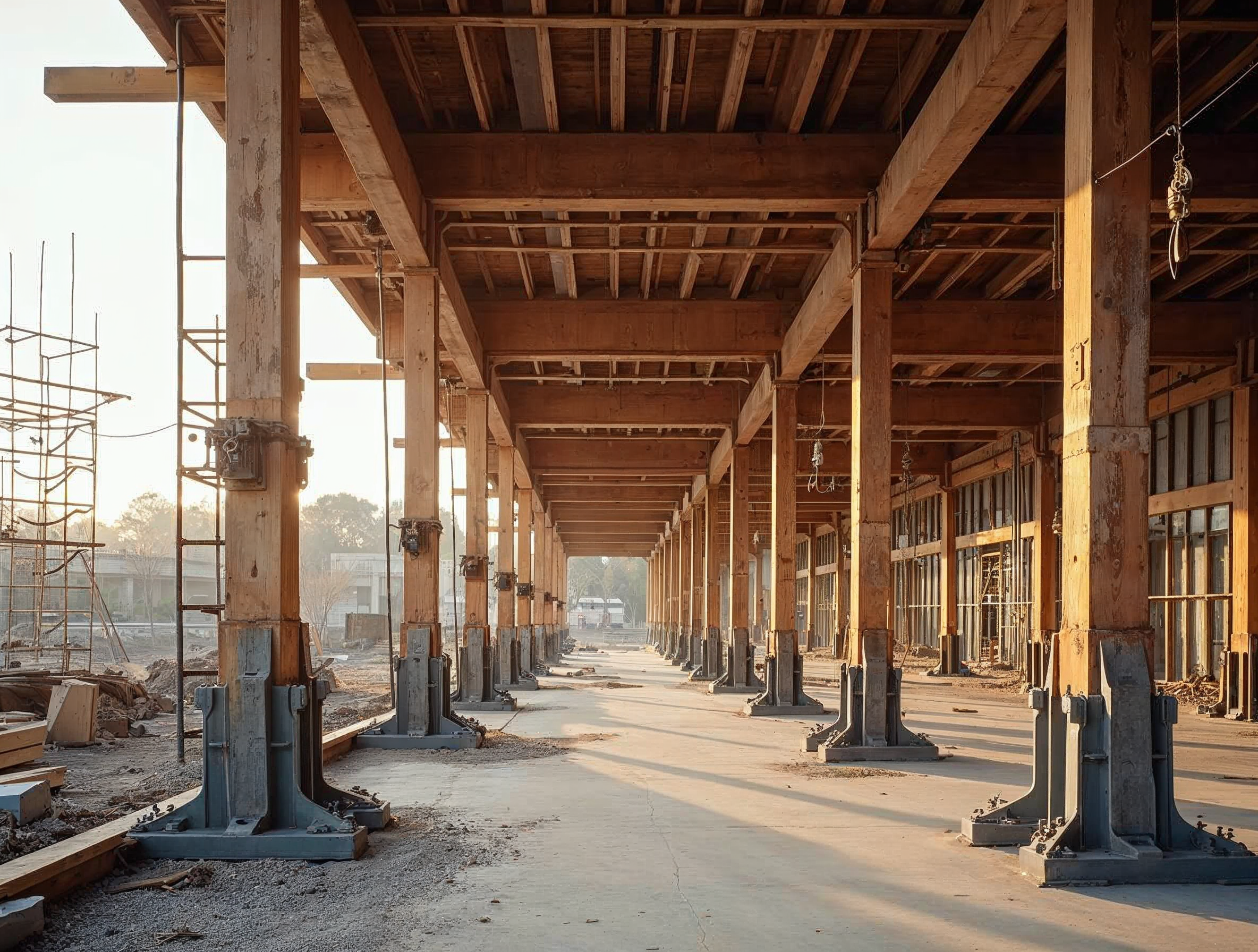
- Shoring Tower Erection: Heavy-duty adjustable steel shores (typically Ellis or Acrow systems rated at 10,000 to 25,000 lbs per leg) are erected on continuous wood mudsills to distribute point loads across the existing floor system.
- Double-Floor Load Transfer: When the slab below cannot support concentrated temporary loads, shoring towers must be mirrored on the floor below, transferring loads directly down to building columns or primary foundation walls.
- Needle Beam Insertion: Core-drilled openings through masonry above the proposed header line receive steel needle beams, which temporarily support the upper masonry course while the opening below is cut.
| Shoring Phase | Technical Requirement | On-Site Verification Method | |---|---|---| | Exploratory Demolition | Non-destructive localized inspection cuts | Ultrasonic testing, rebar scanning & optical borescopes | | Temporary Shoring | 2.5x calculated dead + live load safety factor | Calibrated torque measurements on screw jacks | | Pre-Deflection Jacking | Pre-load beam to 75% of calculated dead load | Electronic dial indicator gauges (0.001" precision) | | Secondary Pinning | Dry-pack non-shrink grout (minimum 5,000 psi) | Visual inspection of complete void fill and 48-hr cure check |
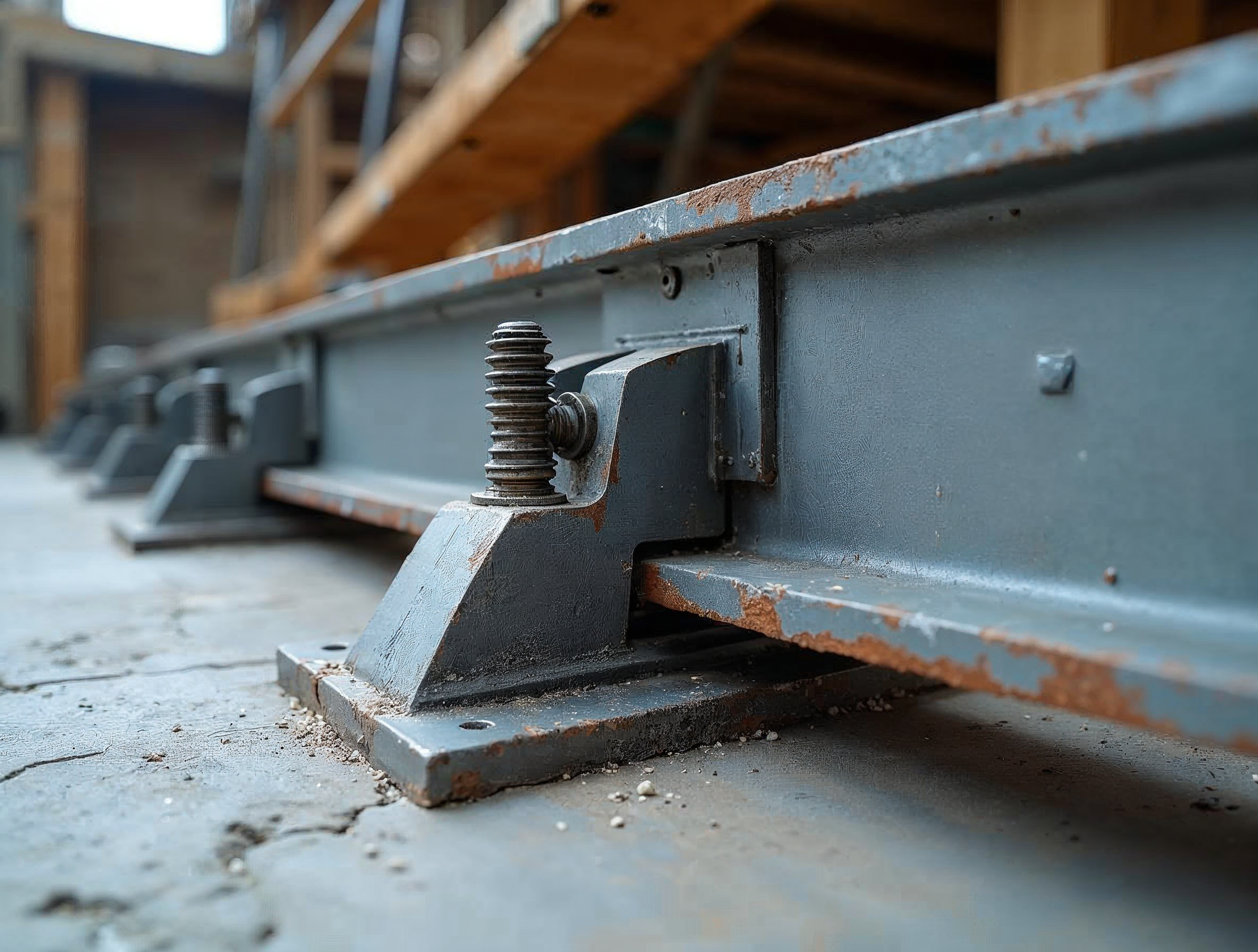
Structural Steel Header & Moment Frame Design
Once the opening is shored, a permanent structural support system is installed to carry the spanning loads:
Deflection Limits That Protect Historic Finishes
Standard building code permits a live-load deflection of L/360. In high-end pre-war renovations, that standard is completely unacceptable; an L/360 deflection across a 16-foot opening allows over half an inch of sag, which will shatter imported marble tile, bind custom millwork doors, and crack brittle pre-war plaster.
TRD Builders engineers all spanning steel headers to an ultra-rigid limit of L/720 to L/1000:
- Maximum allowable live load deflection:
Δ_LL = L / 720 - For a 16-foot span:
Δ_max = (16 × 12) / 720 = 0.267 inches(under 1/4 inch across the full room span)
Moment Frames vs. Post-and-Beam Configurations
When masonry shear walls are removed, lateral stability must be restored. In these instances, our structural team designs a continuous steel moment frame:
- Header Beams: Typically wide-flange structural steel (e.g., W8x31 up to W12x50) sized to fit within pre-war ceiling coffers.
- Vertical Columns: Hollow structural steel sections (HSS 4x4 or HSS 6x6) concealed within finished wall jambs.
- Full-Penetration Welded or Bolted Moment Connections: Engineered to resist lateral wind and seismic shear loads, transferring bending moments safely into base plates anchored to the structural slab or building steel columns.
Pre-Deflection Hydraulic Jacking
Steel beams do not carry load until they deflect. If a new steel beam is installed tight against existing masonry without pre-loading, the masonry above will drop slightly as soon as temporary shores are removed.
To prevent this settlement, we install hydraulic flat jacks beneath the header beam. The beam is jacked upward against the masonry to approximately 75% of its calculated design dead load before base plates are permanently shimmed and dry-packed with high-early-strength non-shrink grout (minimum 5,000 psi compressive strength). When the temporary shores are struck, zero measurable settlement occurs in the ceiling or adjacent units.
NYC Department of Buildings (DOB) & Co-op Board Navigation
A structural wall removal in a Manhattan apartment is classified as a major alteration under the NYC Building Code:
- DOB Filing Classification: Filed through DOB NOW: Build as an Alteration Type 2 (Alt-CO or Alt-2 Full Demolition/Structural) under NYC Administrative Code §28-104.
- Directive 14 Self-Certification vs. Standard Plan Examination: While Directive 14 allows licensed Professional Engineers to expedite plan review, structural removals in pre-war buildings frequently require DOB Structural Plan Examiner audit and Special Inspection filings.
- Required Special Inspections (Chapter 17):
- BC 1704.3: Steel Construction (welding, bolting, material verification)
- BC 1704.4: Concrete Construction (high-strength grout, concrete pedestals)
- BC 1704.20: Structural Stability & Temporary Shoring during demolition
Managing Co-op Alteration Agreements
Co-op boards are fiercely protective of building infrastructure. Their consulting engineers review submissions with exceptional scrutiny. A typical approval timeline includes:
- Alteration Agreement Review (2–4 weeks): Submission of structural drawings, shoring plans, and structural calculations signed and sealed by a NY-licensed PE.
- Neighboring Unit Pre-Condition Surveys: High-resolution photographic and video documentation of adjacent apartments (above, below, and alongside) to establish baseline conditions before shoring starts.
- Vibration & Settlement Monitoring: Optical crack monitoring gauges installed across known plaster fissures in adjacent units during demolition and steel erection.
Precision Field Execution: Partnering for Flawless Interiors
Once the steel is permanently dry-packed, inspected, and signed off by the Special Inspection agency, the structural shell transitions to architectural finishing.
At TRD Builders, our integrated engineering and execution crews coordinate directly with premier residential general contractors and interior finishing partners—including teams like KS Renovation Group, who specialize in historic pre-war apartment transformations. By providing laser-straight substrates, rigid structural tolerances, and flush architectural headers, we enable interior craftsmen to install custom crown moldings, flush pocket doors, and seamless Venetian plaster without fear of future settlement cracking.
Opening up a pre-war space delivers breathtaking natural light and expansive modern layouts—provided the hidden engineering beneath the surface is executed with uncompromising discipline.